5. Methods and Examples: Navigation, Position Fixing and Datum#
Marine survey techniques are primarily used to investigate underwater archaeological sites to assess importance, develop management strategies, and to provide information to assist in site stabilisation and preservation. While a number of sensor and data acquisition systems are used, such as light and acoustic systems, what is common to all is the necessity to know where the survey instrument is in relation to the survey vessel and to the wider world. Therefore, the first step in processing various forms of marine survey data is normally to ensure that positional information has been applied and that any navigational corrections that may be needed have been made and appropriately documented.
5.1. Navigational Files#
Producing maps of the ocean-floor onboard moving marine vessels usually requires access to Global Navigation Satellite Systems (GNSS)-aided inertial positioning systems which provide accurate position, heading, attitude, heave and velocity data for both the survey vessel and deployed survey equipment. The hardware and software are designed to integrate with the marine survey data acquisition software and can provide centimetre-level accuracy. It is also possible to ‘post process’ logged GNSS data to improve accuracy from the standalone 10m to around 10-2cm.
Examples of positions systems include standalone GNSS, no offsets accounted for; Differential Global Navigation Satellite System (DGNSS); Real Time Kinetic (RTK) – DGNSS; Post processed GNSS; Wide Area Differential Global Positioning System (WAGPS) or Wide Area Differential Global Navigation Satellite System (WADGNSS)(UKHO 2020).
The Universal Transverse Mercator or UTM projection is recognised as the mapping standard by many marine survey companies. The UK is covered by three UTM zones: zone 29 (central meridian 9 degrees west), zone 30 (central meridian 3 degrees west) and zone 31 (central meridian 3 degrees east). It is important to note the UTM zone of the mapping and the underlying ellipsoid that has been used for the UTM projection (e.g. WGS84) in Metadata.
All survey depths need to be adjusted for tide. This means adjusting soundings to the relevant local chart datum (CD) which is usually Lowest Astronomical Tide. Observed tides should be used, rather than predicted tides. Very accurate GNSS systems can provide tidal height, otherwise an appropriate model such as Vertical Offshore Reference Frame (VORF) should be used. Predicted tides can be obtained from Admiralty Tide Tables, TotalTide and EasyTide products.
For more information on Co-ordinate Reference Systems (CRS), please see ‘Projections and co-ordinate systems’ in the ADS Good Practice Guide for GIS .
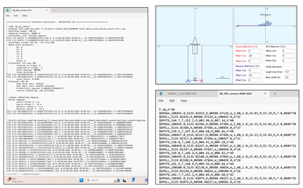
Fig. 5.1 Navigation files created by Geosuite software – Log (left), layback calculator (above right), and raw navigation files generated by the Trimble DGPS 12 channel receiver (below right). © IMARDIS Bangor University#
5.2. Diver Tracking Systems#
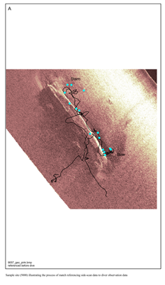
Based on applied acoustics, the underwater tracking of archaeologists undertaking site inspections creates another form of positional data which, while often prone to error, can form a useful component of the final digital archive. Such systems consist of a topside console, a transceiver mounted on a pole extended into the water, and a positioning beacon located on the diver. An acoustic pulse is transmitted to the positioning beacon which replies and then the transceiver calculates the range to the diver, the bearing and the depth. Combined with the diver’s communications logs and video, the ground-truthing of surface anomalies can be undertaken. Typical outputs are track plots which can be overlain on georeferenced side-scan or single/multi-beam echosounder images.
Case Study: Wrecks on the Seabed, Round 1, Year 1
Wessex Archaeology dived nine sites utilising a diver tracking system. The diver’s position was achieved by the integration of the tracking system’s acoustic technology and differentially corrected global positioning system on board the vessel. The tracking system comprised an ORE LXT Ultra Short Baseline (USBL) system integrated with a Leica MX420 Differential Global Positioning System receiver and a KVH Autocomp 1000 fluxgate compass; an acoustic hydrophone fixed over the side of the vessel and a transponder attached to the diver. A georeferenced side-scan image was generated prior to the diving operation and the locations of the diver’s spoken observations, video footage from the diver’s helmet -mounted camera, and still photographs could then be attached to the diver track in GIS software (ArcView). The reports are archived with the Archaeology Data Service (https://doi.org/10.5284/1000316).