
4. Creating the Digital Archive#
4.1. Data Selection: Deciding what to Archive#
During the course of a project data may be generated that might not be considered as suitable for inclusion in the final project archive. For example, the patch text and the sound velocity test where system adjustments might be made to counter ‘smiles’ or ‘frowns’ in the data where the outer beams of sound are moving faster or slower than assumed. It is also common to run a few survey lines over the top of a known object to also check motion sensors, with errors in tidal adjustment manifesting as mismatched survey lines.
Whilst many elements of data acquisition and processing may be automated (e.g. use of Python scripts), practitioners emphasise the necessity of maintaining a manual surveyor’s log, where the key information is entered about location, date, file name, and where errors and potential problems are recorded as the survey progresses (e.g. an increase in sea state causing distortion).
For example, all modern bathymetric instruments (e.g. single-beam echosounder, multi-beam echosounder and LiDAR) record ‘noise’ – these distortions can be caused by air bubbles in the water, seaweed, fish, caught net and other things affecting the signals. Complex structures like masts can give a weak return, and so they could be assumed to be noise or mid-water features like fish. Sometimes data can be over cleaned and real archaeological features accidentally removed. This can happen if an automatic cleaning tool has been used and the results not fully checked. There may be a need to return to the earlier processed forms of the data set to correct and make sure all archaeological information has been extracted.
While retaining all data from a project is always the safest option - and may be a requirement in some instances - for data sets that undergo multiple processing steps archiving the ‘start’ and ‘end’ points while recording in detail the connecting steps can ensure that data is reproducible and can be verified. Hence, practitioners suggested a preference for archiving the navigationally corrected ‘raw’ data files and the final data products – providing, of course, the metadata recorded for the project contains the sufficient details of all processing (including software and hardware details, processes and steps, so that a user is able to recreate the intermediate phases. This is discussed further in the ‘Preservation intervention points for marine data’ section below and more generally in the ADS Guides to Good Practice section on ‘Data selection: preservation intervention points’.
The development of inhouse procedural notes to ensure standardised processing has also been emphasised as particularly useful for appraising the usefulness of data received. Keeping a log of the settings during each phase of processing ease the compilation of detailed metadata and can be included within the archival data set. Structured metadata and documentation is discussed further in the Metadata and Documentation section below.
4.2. Structuring your Archive#
General guidance on structuring digital archives is available in the ADS Guides to Good Practice section on ‘Planning for the creation of digital data’. Additionally, the British Geological Survey have created detailed guidance on storing survey data within a standardised folder structure (BGS 2020). One core principle however is to assume that those working with your data come from a position of knowing very little about the project that generated it. Making directory and file names obvious in terms of what they are and what they contain is one basic step that can help make complex data sets understandable and navigable in the long term. This can include adding some means of identifying the relevant activity to the file name such as a unique reference number, project number, or project name to create a standardised naming convention e.g. for survey line increments:
[Survey ID/Survey Name][Survey Year](Instrument][Incremental line identifier].(File Format Extension]
Additionally, having different folders numbered or identified by phases such as acquired data, navigational corrected data, and full interpreted data, allows processed data to be easily distinguished so that a regression can be made if needed, for example:
[Survey ID/Survey Name]_[Survey Year]_SSSraw
Beyond this, structuring a project folder so that it has folders for different elements, such as report writing, correspondence, bibliographic searches, Data In and Data Out, logs and metadata etc., from the outset allows project members to easily navigate the project data, save data to the right locations, and know where to access elements they may need at any time. This approach also makes it easier to identify data to be archived when the time comes for deposition. Inclusion of readme.txt or manifest files within the archive and component directories can also provide contextual information for subsets of data, describing the overall structure and listing files independently of higher level metadata records.
4.3. Preservation Intervention Points for Marine Survey Data#
The delivery of marine projects often involves data transformation by processes such as down-sampling, aggregation, annotation, and format migration. For example, multi-beam echosounder data may start out as a series of pings, position, altitude, tide measurements and sound velocity profiles, which are typically used to produce a gridded data set, which can feed into the representations as seabed contours. Parts of this workflow (e.g. apply marrying positioning and altitude to georeferenced measurements) can be undertaken in real-time during the acquisition process, but other elements are done during post-processing.
Whilst practitioners have suggested a preference for archiving the navigationally corrected ‘raw’ data files and the final data products, it may also be desirable to preserve data from intermediate stages if a great deal of additional manipulation and manual interventions have had to be undertaken. As stated above, maintaining and archiving a detailed log of these processes can provide transparency and aid in selection for deposition.
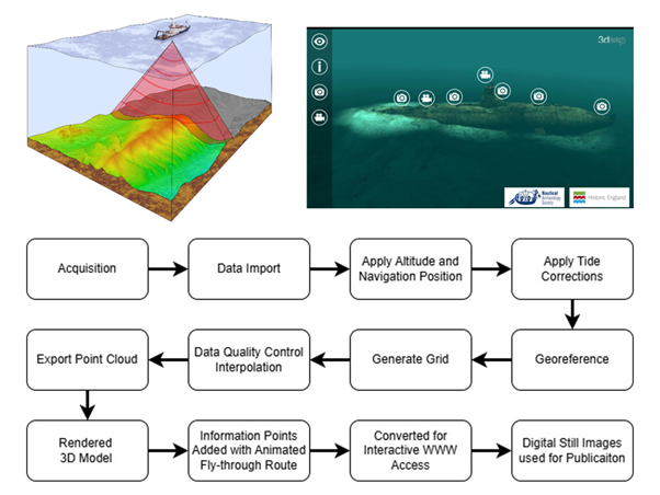
Fig. 4.1 Workflow for creation of an interactive 3D rendered model from multi-beam echosounder data, video footage and digital photographs. Multibeam survey image ©SEACAMS Bangor University (O Dan y Dŵr, SEACAMS 2). 3D model of A1 submarine © Nautical Archaeology Society and Historic England (A1 Submarine Dive Trail, Nautical Archaeology Society).#
4.4. Data Processing and Formats#
This processing to form ‘new’ data sets poses several archival issues in terms of selection and retention and an overview of file formats related to the phases of processing and interpretation is shown below. An underlying principle however is that raw data sets will almost always form the basis of the archived data set with derived products being selected for archive according to purpose, reuse potential, and ease of preservation. It is important to identify from the outset data formats that will be suitable for long-term preservation and to distinguish between these and formats that are used for short-term data collection and processing. Many repositories require data to be deposited in formats that are open, standardised, and often non-proprietary or software-specific to allow for long-term access and reuse. Export to such formats may or may not be possible at various stages in the data lifecycle. It is recommended that both proprietary and open format exports are stored and offered for archiving, particularly for complex survey data where elements may not be successfully exported to an open format.
For more about the archiving of Digital Photographs, see the ADS Guide to Raster Images.
For more information about the archiving of Digital Video, see the ADS Guide to Digital Video.
For more information about the archiving photogrammetric surveys, see the ADS Guide to Close-range Photogrammetry.
For more information about the archiving data from Oceanographic Data Loggers, see the British Oceanographic Data Centre submission guidance.
Imagery |
||
|---|---|---|
Technique |
Typical Output Formats |
Preferred Archival Formats |
Photography |
Can include a range of generic raster images types (.jpg; .tiff; .dng) alongside proprietary camera formats: .gpr (GoPro RAW); .crw, .cr2, or .cr3 (Canon); .raw, .nef or .nrw (Nikon); .pef or .ptx (Pentax); .raw or .rwl (Leica) |
.tif; .jpg; .dng |
Photogrammetric models |
Often comprising a range of files including images (see above) alongside proprietary project files such as .psx (Agisoft Metashape). Exports can be in a range of generic or proprietary 3D formats including .dae; .stl; .ply; .igs; .fbx; .max; .dwg; .3ds; x3d |
.x3d; .obj (ascii), .ply (ascii). Source images must be included in the archive together with sample views of the 3D model as digital stills (see Photography formats above). |
Video and audio |
.mpg (MPEG, MPEG-2, MPEG-4); .mov; .bwf (Broadcast Wave format). Audio: .wav (Waveform audio) |
.mpg; .mp4; .mkv; .mov; bwf; .wav |
Navigation, Position and Datum |
||
|---|---|---|
Technique |
Typical Output Formats |
Preferred Archival Formats |
Navigational Position Files |
Text or delimited text as .txt or .csv |
.txt; .csv |
Diver Tracking |
.txt; .csv |
.txt; .csv |
Phase 1: Navigation Corrected Data |
||
|---|---|---|
Technique |
Typical Output |
Preferred Archival Formats |
Bathymetric LiDAR |
.las; .txt |
.las; .txt; .csv |
Underwater Laser Systems Laser Scanners |
.xyz; .csv; .las; .e57 |
.xyz; .csv; .las; .e57 |
Stereo Cameras: |
.jpg (8-bit processed images); .tif (12-bit raw images) |
.jpg; .tif; .dng |
Side-scan sonar |
.xtf (Extended Triton format) |
.xtf |
Single-beam echosounder |
Raw data in proprietary format |
.xtf |
Multi-beam echosounder |
ASCII text as individual lines as .txt; .csv; .pts; .asc |
.txt; .csv; .pts; .asc |
Magnetometer |
.txt; .csv; .pts; .asc or .xyz |
.txt; .csv; .pts; .asc; .xyz |
Chirp |
.sgy/.segy (SEG-Y) |
.sgy/.segy |
Boomer |
.sgy/.segy |
.sgy/.segy |
Parametric (non linear) echosounder |
.xtf, .txt |
.xtf; .txt |
Trackplots |
.shp (Shapefiles including .shx, .dbf, etc. associated files); .dxf, .dwg (CAD); .gml (Geography Markup Language) |
.shp (including .shx, .dbf, etc. associated files); .dxf; .dwg; .gml |
Oceanographic Data Loggers |
Simple tabular data of time series and variable named columns from proprietary software for instrumentation e.g. Fathom for Seabird SBE 911plus instrument |
Text or delimited text as .txt, .tab or .csv; .nc (NetCDF); Open document spreadsheets .ods; Excel .xlsx |
Phase 2: Processed Data |
||
|---|---|---|
Technique |
Typical Output |
Preferred Archival Formats |
Bathymetric LiDAR |
Proprietary formats such as .ecw (Enhanced Compression Wavelet); .las (laser file format; point cloud); .pts (Laser scan plain data format); .e57 |
.las; .pts; .e57 |
Underwater Laser |
.las (laser file format; point cloud) |
.las; .pts; e57 |
Side-scan sonar |
Mosaic or coverage map |
.tif (GeoTiff) |
Single-beam echosounder |
Raw data in proprietary format |
.xtf |
Multi-beam echosounder |
Grid point clouds; Digital elevation models |
ASCII as individual lines .txt; .csv; .pts; .acs or as point cloud .txt; .csv; .pts; .asc; .las, .e57 |
Magnetometer |
ASCII as individual lines (.txt, .csv, .asc) |
.txt; .csv; .asc |
Chirp |
.sgy/.segy |
.sgy/.segy |
Boomer |
.sgy/.segy |
.sgy/.segy |
Parametric (non-linear) echosounder |
ASCII |
|
Trackplots |
.shp (including .shx, .dbf, etc. associated files); .dxf, .dwg |
.shp (including .shx, .dbf, etc. associated files); .dxf, .dwg |
Oceanographic Data Loggers |
Complex tabular data; Blue Programming .bl; .hex; .xmlcon; .hdr |
Netcdf .nc; Matlab .mat; SPSS portable format .por or .sav; Stata .dta; .csv |
Phase 3: Gridded, sub-sampled and visual output |
||
|---|---|---|
Technique |
Typical Output |
Preferred Archival Formats |
Bathymetric LiDAR |
Gridded point clouds; Digital Elevation Models; Raster (no elevation data); Contours |
Digital Elevation Models or Mosaic images as GeoTiff (.tif) |
Underwater Laser |
Gridded point clouds; Digital Elevation Models; Raster (no elevation data); Contours |
.las; .pts; .e57 |
Side-scan sonar |
Mosaic; Coverage Image |
.tif (GeoTiff or standard Tiff with .tfw world file) |
Multi-beam echosounder |
Gridded point clouds; Digital Elevation Models; Raster (no elevation data); Esri grid; Contours |
.txt; .csv; .pts; .asc; .las; .tif (GeoTiff or standard Tiff with .tfw world file). Other formats .fir; .bag; .asc; .grd; .adf; .shp (including .shx, .dbf, etc. associated files) |
Magnetometer |
Gridded processed data; Altitude total field; Residual grid; Contours |
.txt; .csv; .pts; .asc; .las; .tif (GeoTiff or standard Tiff with .tfw world file), ASCII grid .asc. Other formats .grd; .shp (including .shx, .dbf, etc. associated files) |
Chirp |
.sgy/.segy |
.sgy/.segy |
Boomer |
.sgy/.segy |
.sgy/.segy |
Parametric (non-linear) |
3D models/volumes |
ASCII .txt |
Oceanographic Data loggers |
Geospatial data – vector and raster |
.shp (including .shx, .dbf, etc. associated files); Keyhole markup language .kml; .tif (GeoTiff or standard Tiff with .tfw world file); CAD data .dwg, .dxf or .svg; Geography markup language .gml |
Phase 4: Interpreted Outputs |
||
|---|---|---|
Technique |
Typical Output |
Preferred Archival Formats |
Bathymetric LiDAR; Underwater Laser Systems; Side-scan sonar; Magnetometer |
Identified anomalies (points or areas); Anomaly images (from plots) |
.shp (including .shx, .dbf, etc. associated files); Gazetteer .csv; .tif; .jpg; .png |
Chirp; Boomer; Parametric (non-linear) echosounder |
Identified anomalies (points reflector); Profiles (complete or partial); Horizon image with elevation data; Horizon (grid); Horizon images |
.shp (including .shx, .dbf, etc. associated files); Gazetteer .csv; Raster .tif; .jpg; .png; .gtiff; .tiff; ASCII grid .asc; Other formats .grd; .tif; .jpg; .png |
Phase 5: Reporting and Publication |
||
|---|---|---|
Technique |
Typical Output |
Preferred Archival Formats |
Bathymetric LiDAR; Underwater Laser Systems; Side-scan sonar; Magnetometer; Chirp; Boomer; Parametric (non-linear) echosounder; Oceanographic Data Loggers |
Online 3D Models (e.g. Sketchfab), Text, Illustrations (e.g. AutoCAD), Imagery, Presentations |
.obj; .las; .txt; .docx.; .odt; .html; .dwg; .dxf; .svg; .tif; .jpg; .png; .dng; .pdf |
4.5. Metadata and Documentation#
Metadata for marine survey projects should be recorded at several levels (e.g. project level, survey level, etc.) to form a set of comprehensive documentation for the data produced. Many repositories will have their own metadata requirements at project or collection level for deposited data sets, and for specific types of data contained within these data sets. In addition to meeting the requirements of the designated repository, this guide recommends the use of the MEDIN Data Guidelines for documenting the various survey techniques used.
MEDIN has produced a series of templates which contain detailed descriptions of metadata fields, how to complete them, and samples of daily logs which collate information in such a way as to allow the easy completion of metadata for archival deposition. Templates are available from MEDIN for bathymetric, seismic data, geotechnical investigations, grab and core samples, magnetometer data, and for imagery. The templates generated for each type of operation or instrument contain additional specific fields to include settings, ranges, information about interpolation applied, survey personnel, processing and quality control.
Examples of the key fields for the completion of General Project and Survey Metadata records are shown below:
Example MEDIN Project Metadata |
||
|---|---|---|
Metadata fieldname |
Completion Requirement |
Format & Controlled Vocabulary |
Project Name |
Mandatory |
Free text |
Project Code |
Mandatory |
Free text |
Project Start Date |
Mandatory |
Date; yyyy-mm-dd |
Project End Date |
Conditional |
Date; yyyy-mm-dd |
Project Website |
Conditional |
URL |
Example MEDIN Survey Metadata |
||
|---|---|---|
Metadata fieldname |
Completion Requirement |
Format & Controlled Vocabulary |
Survey Name |
Mandatory |
Free text; |
Survey Type |
Mandatory |
Free text or Controlled Vocabulary; OGP SSDM WORK_CATEGORY Domain; |
Survey Abstract |
Mandatory |
Free text; |
Survey Code |
Mandatory |
Free text; |
Originator |
Mandatory |
Controlled vocabulary: European Directory of Marine Organizations |
Owner |
Mandatory |
Controlled vocabulary: European Directory of Marine Organizations |
Survey Start Date |
Mandatory |
Date or DateTime; yyyy-mm-dd or yyyy-mm-dd hh:mm:ss |
Survey End Date |
Mandatory |
Date or DateTime; yyyy-mm-dd or yyyy-mm-dd hh:mm:ss |
Time Zone |
Mandatory |
Free text; |
Spatial CRS |
Mandatory |
Controlled Vocabulary; EPSG Geodetic Patameter Dataset |
Original CRS |
Conditional |
Controlled vocabulary; EPSG Geodetic Patameter Dataset or other defined coordinate reference system register; |
Transformation |
Conditional |
Free Text |
Position Fix |
Mandatory |
Free Text |
Horizontal Accuracy |
Conditional |
Decimal; units = metres |
Depth Co-ordinate Reference System |
Mandatory |
Controlled Vocabulary; EPSG Geodetic Patameter Dataset |
Vertical Accuracy |
Conditional |
Decimal; units = metres |
Platform Type |
Optional |
Controlled vocabulary: SeadataNet Platform Classes, Table L06 |
Platform Name |
Conditional |
Controlled Vocabulary; ICES Reference Codes, Table SHIPC |
Cruise Report Reference |
Optional |
Free text; in reference format. |
Confidentiality |
Optional |
Free text; |
As highlighted in the MEDIN examples above, the specification of standardised formats for metadata entry, e.g. date formats and units of measurement, are a key component of capturing accurate and useful metadata. Additionally, controlled vocabularies should be specified to ensure consistent and well-defined use of terms. Further to the examples listed in the MEDIN Data Guidelines, the Forum on Information Standards in Heritage FISH have developed a number of controlled terminology lists useful for recording aspects related to marine survey. These include the archaeological Event, Maritime Craft, Evidence, Cargo, and Archaeological Objects thesauri. These terminology lists should be used wherever possible to promote consistency of description across data sets and improve searchability.
In addition to using formal metadata specifications, this guide strongly recommends the inclusion of log files and processing documentation in archived data sets. These files may range from informal free text documents and notes through to formal processing or settings reports generated by specific software applications. Such documentation can provide additional context to formal metadata as well as recording information that may not be required by formal metadata specifications.
Sitting alongside the Data Guidelines, MEDIN’s Discovery metadata standard contains information that accompanies a data set and allows users to discover the data set’s contents, provenance, and access conditions. It is a fundamental element of the previously-discussed FAIR Principles. The organisations making up the MEDIN DAC network have collaborated on the development of key fields of information which are standard across all the organisations, and which comply with the UK government GEMINI2 standard and international conventions such as INSPIRE and ISO19115.
4.6. Copyright Considerations for Marine Survey Data#
Digital archivists and repository managers stress the need to be fully aware of all the clauses of any data licences you may have entered. These may place limitations on derived data, its archiving and supply to other users by repositories and archiving organisations.
Restrictions can range from simply placing an acknowledgement and licence number on any derived data sets, through to strict restrictions on how much of an original data set can be reproduced and the methods of reproduction. Copyright issues should be identified and clearly documented as early as possible in a project. Clearances and written permissions from any third-party copyright holders may need to be obtained and documentation provided to the MEDIN DAC on deposition of the data set.
4.7. Importance of Developing an Archiving Plan#
The complexity of some projects may require developing knowledge of the archiving requirements of more than one repository. It is important to anticipate this and make yourself familiar with what they will need from you to safely and securely preserve your data, and to make it available to others. Such considerations are often key components of overall Data Management Plans. Where components may be split across multiple repositories it is important to plan for the mutual referencing of these using, where possible, permanent identifiers (PIDs) such as Digital Object Identifiers (DOIs). This is equally important where the physical and digital archive are stored separately and museum or archive IDs can be used to tie such elements together.
Case Study: London Gateway Port: Channel Clearance, Dredging and Capital Dredging Project
The project area for capital dredging for the new port was just over 100km in length and varied between 360m to 1km in width.
A variety of investigation methods utilised over the span of the project which ran from 2006 until 2016 included diver observation, geophysical survey and capital dredging watching brief, and object reporting. As a result of the various phases of fieldwork over 40 archaeological sites of varying complexities were investigated, over 400 geophysical anomalies were identified, and over a thousand archaeological objects were recovered. Southend Museums Service have accessioned most of the finds and associated archive (Accession ID: SOUMS: A2018.4-5) which includes geophysical data, digital photographs, project / fieldwork / diving generated data, reports, x-rays and research. The Archaeology Data Service collection comprises the additional project reporting undertaken during the project.